


 Reply With Quote
I wrote this if that's too complicated then where's the problem? i'm happy to help
The circuit is easy to build using only simple components, there are nice big places to solder to, easy
Results 1 to 10 of 12
-
September 12th, 2005, 07:58 #1DCEmu Newbie


- Join Date
- Jan 2005
- Location
- Washington State
- Age
- 34
- Posts
- 97
- Rep Power
- 0


 is there a more detailed internal VGA guide?
I'm dying to do this mod, but, having a hard time finding a very good guide. My problem is mostly getting the VGA circuit. So maybe someone could direct me to the construction of a VGA circuit and then a little rundown of rigging it in the DC? Thanks in advance.
-
September 12th, 2005, 15:22 #2DCEmu Pro

- Join Date
- Jan 2005
- Location
- london
- Posts
- 840
- Rep Power
- 75
-
September 12th, 2005, 22:42 #3DCEmu Newbie
- Join Date
- Jan 2005
- Location
- Washington State
- Age
- 34
- Posts
- 97
- Rep Power
- 0
Well, the big problem is that I have a hell of a time reading schematics.
-
September 13th, 2005, 16:14 #4DCEmu Pro
- Join Date
- Jan 2005
- Location
- london
- Posts
- 840
- Rep Power
- 75
Do you not have any experience? that schematic is really simple. What dont you understand? do you know what the symbols mean?
If you want i can walk you through it, i can tell you step by step what to solder and where etc. would that help?
-
September 13th, 2005, 23:09 #5DCEmu Newbie
- Join Date
- Jan 2005
- Location
- Washington State
- Age
- 34
- Posts
- 97
- Rep Power
- 0
I've used schematics before, but even simpler ones. For guitar. I'm really handy with a soldering iron, but, I just don't really know anything incredibly technical. Originally Posted by ptr.exe
-
September 14th, 2005, 16:00 #6DCEmu Pro
- Join Date
- Jan 2005
- Location
- london
- Posts
- 840
- Rep Power
- 75

Okay well...
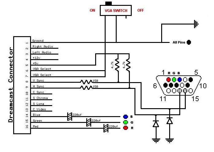
Just to make sure; Where one line crosses another that does not mean they connect on the circuit, only when there is a spot do they connect.
Do you understand the RGB bit? you just put a 220uF capacitator in between where the signal is coming from at the DC to where its going to the VGA socket, you solder one leg to the side with the DC and solder the other leg to the VGA side. You do this for each of RGB, then connect them all to the VGA socket, in the correct place.
Next is the sync bit, its a bit more complicated. For each; put a 150 ohm resistor in line from the signal from the DC, then after that take a 4700 ohm resistor solder one end to the +5V and the other end to the sync wire after the 150 resistor. Then take a diode and have the black end (depends on diode but most are like this, if not then which ever is the +ve end) soldered to the sync wire and the other end to ground (-ve). After that solder the wire to the socket in the correct place.
Do that for each sync.
Then you need a VGA switch. To tell the DC to make VGA pin 6 and 7 need to be grounded, so have a switch that can connect them to ground (-ve) so you can turn it off to use the DC on a TV.
And ground every black dot on the VGA socket.
Does that help? i can show you an example circuit drawn in bitmap, if you really cant picture this.
-
September 15th, 2005, 23:12 #7DCEmu Newbie
- Join Date
- Jan 2005
- Location
- Washington State
- Age
- 34
- Posts
- 97
- Rep Power
- 0
An example circuit would be a great help. I'm a really visual person. If it's not too much trouble to do that, anyhow.
-
September 16th, 2005, 15:51 #8DCEmu Pro
- Join Date
- Jan 2005
- Location
- london
- Posts
- 840
- Rep Power
- 75
I'll start on it now and post later

i'll draw one on those plain boards that have strips of copper going across, you know the ones?
-
September 16th, 2005, 16:16 #9DCEmu Pro
- Join Date
- Jan 2005
- Location
- london
- Posts
- 840
- Rep Power
- 75
Okay here...
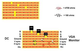
First get a board and scratch off the copper in the places shown. then solder in the components, then solder wire going to the DC on the left and wire going to a VGA socket on the right.
Now just make that circuit and that's it.
EDIT: Just realised that it's quite small, if you copy and paste it into MSpaint or something and enlarge it, that may help.
Also those white things are diodes maybe should of made that more clear.
-
September 16th, 2005, 16:28 #10DCEmu Coder
- Join Date
- Oct 2004
- Location
- Three rivers, ca
- Posts
- 190
- Rep Power
- 73
you should tell him more precisely in what way he should solder the diodes, maybe he don't know they are polarized.
Thread Information
Users Browsing this Thread
There are currently 1 users browsing this thread. (0 members and 1 guests)

Bookmarks